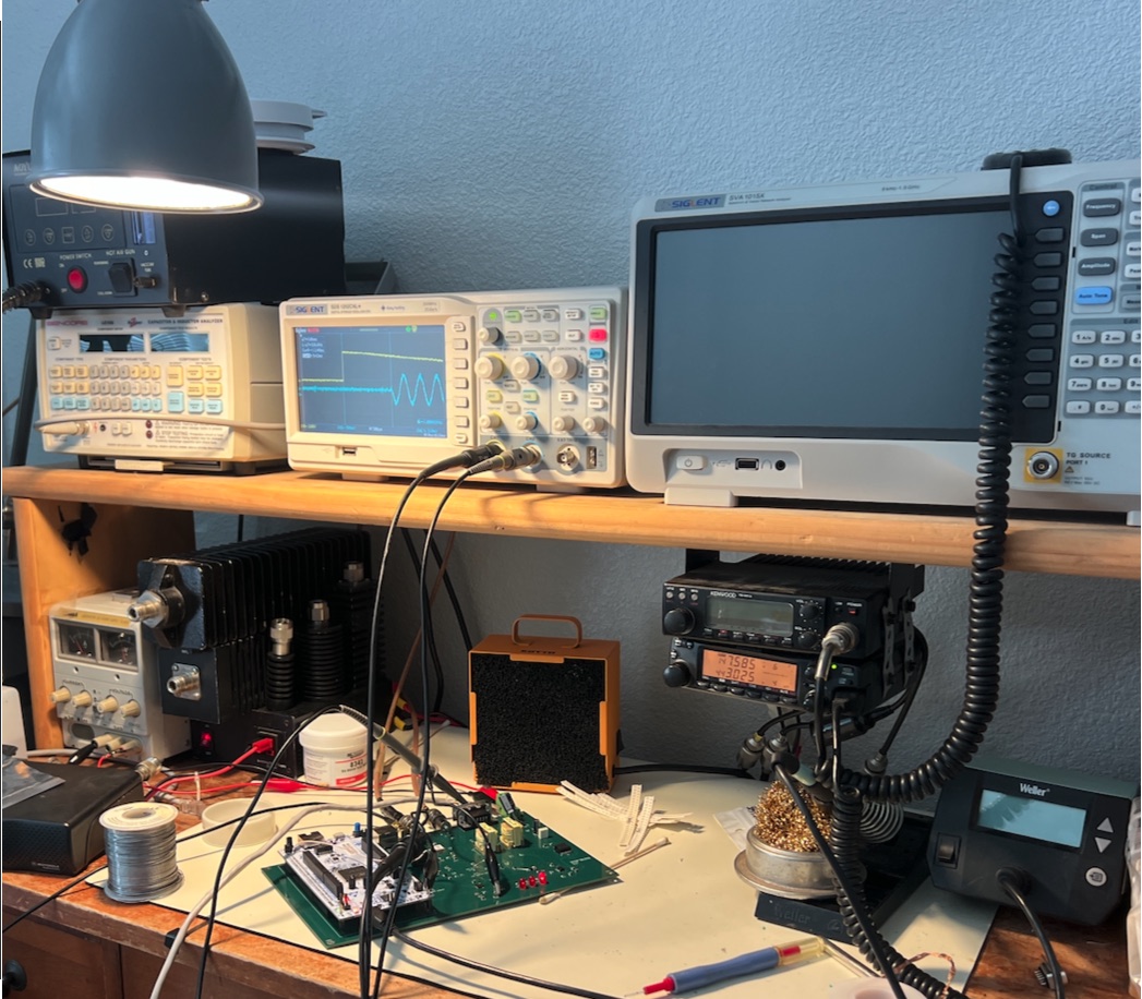
In the last post I said I’d tell you more about the SV-180.
Most AllStarLink voted and simulcast systems run on the VOTER board Jim Dixon designed around 2011, or the RTCM, its production version from Micro-Node. It was a good design for its day and it’s still very good at what the name says: voting, which is picking the best of several receivers. Simulcast transmit is a harder job, and the RTCM was never really built for it.
- The audio timing comes from the board’s own quartz crystal. GPS checks that clock once a second, and if it has drifted too far the board drops sync, but nothing steers it back onto frequency. AllStarLink’s simulcast guide says a transmit board must be fed an external GPS-locked 9.6 MHz signal, and warns that the internal clock’s jitter can make the PL tone warble.
- It’s 2011 hardware: a 16-bit microcontroller with 16 KB of memory and 10 Mb/s Ethernet. You set it up from a text menu over telnet or a serial cable. There’s no web page and no encryption.
What we could do with newer parts and a fresh design
Starting over with a modern processor let me fix those issues and build somthing that better fits our needs.
- The whole audio clock tree is built from the GPS reference’s 10 MHz, so the boards audio clock tree runs at exactly 8,000 samples a second.
- Everything is on a web page: live status, settings and an event log. There are setup wizards for receive level, transmit deviation and RSSI calibration. You update the firmware from the browser, and the board keeps the old version in case the new one doesn’t work out.
- WireGuard is built in, so audio and management traffic are both encrypted.
- It reads status from the site’s GPS reference (several common models work), and it can pass a serial port through to the network so you can manage other equipment at the site remotely.
- Support for an internal GPSDO.
What the SV-180 does
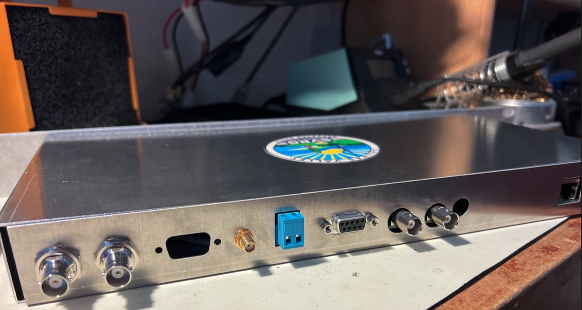
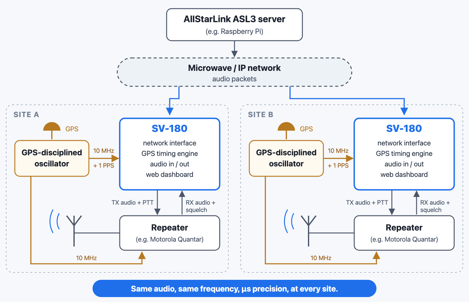
There’s one SV-180 at each transmitter site, sitting between the network and the radio. The ASL3 server sends audio to every site as a stream of packets. The SV-180 doesn’t play a packet the moment it shows up. It buffers it, times it, then launches the audio at an exact moment set by GPS time. Every site does the same thing, so every site transmits in phase at the same instant. The board has two audio buffers one is for a jitter buffer, the other is our launch delay value, settable in 5 ns increments.
It also listens to the repeater’s receive audio and squelch signal, and a DSP routine measures the signal-to-noise ratio of whoever is talking and sends that value to the voter to select the best signal.
How the timing works
Any IP network has jitter, whether it runs over microwave or fiber. Packets take a different amount of time every trip, and sometimes they show up in bursts. If each site played audio the instant it arrived, no two sites would ever line up and the repeater would sound like a box of angry bees.
So the SV-180 keeps when audio arrives separate from when audio plays. A small buffer soaks up the network’s hiccups, and the audio then plays out against the site’s GPS clock. A GPS-disciplined oscillator uses the satellite timing signals to keep a local oscillator extremely accurate, and it hands the SV-180 two things: a very stable 10 MHz and a pulse once per second. With those, a unit on one mountaintop and a unit on another agree on the time without ever talking to each other.
How close is close enough? On the bench, two SV-180s fed from the same GPS reference lined up to within a nanosecond.
From prototype to production
The first SV-180 firmware ran in July 2026, and the hardware has been through three revisions since.
- Rev A was the first prototype: a carrier board for an off-the-shelf processor module, with our audio, GPS and radio circuits around it. All it had to do was prove the idea could work.
- Rev B took what I learned on A and put it into a second board, still built around the plug-in module. I hand-assembled five of them and validated them in early September. Two went to Fremont Peak and Presson Hill for real-world testing while I designed and finalized rev C.
- Rev C is the first production board. The plug-in module is gone, the processor and Ethernet are part of the board itself, and the boards are now machine-assembled. The first C1 was running in October and matched the timing of the B1. Rev C boards have since replaced the rev B boards in the field.
Writing firmware for a board nobody has built
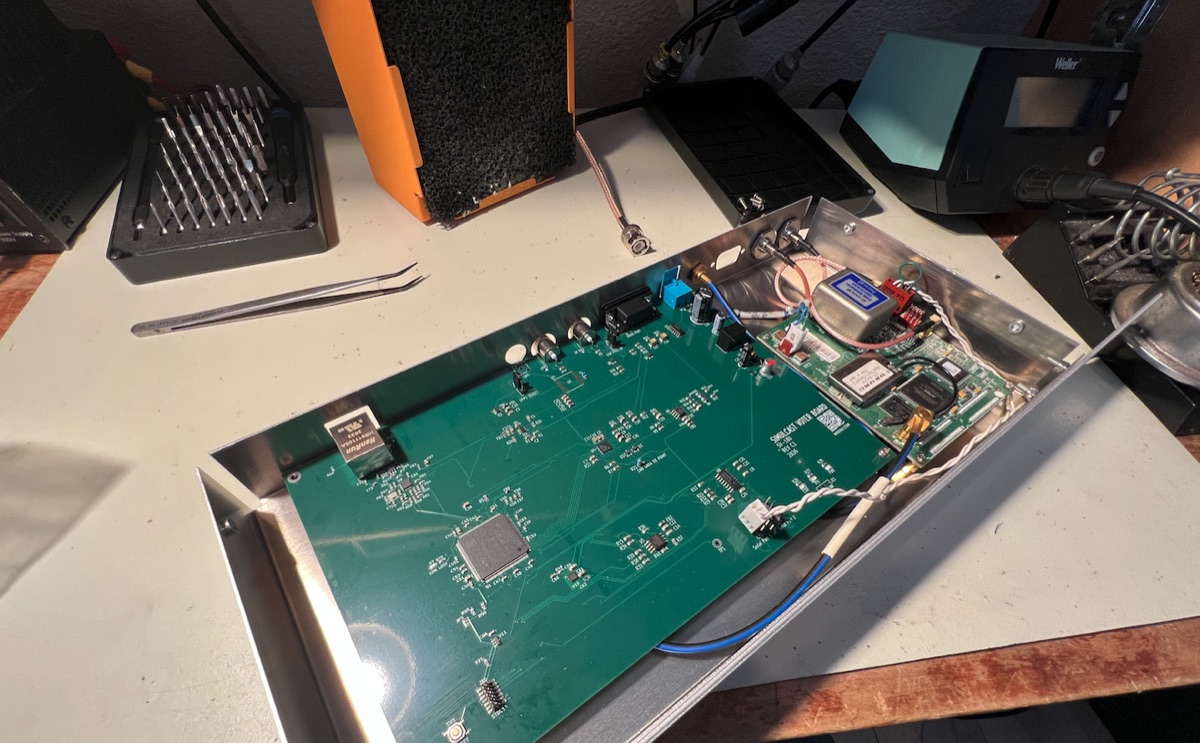
When the board is brand new and something doesn’t work, you can’t tell whether the bug is in the code or in the copper. This was my first real venture into hardware engineering, and I learned that early. Luckily most of my problems turned out to be in the code. There were a few small mistakes in the codec circuit on rev A that could have caused a codec failure!