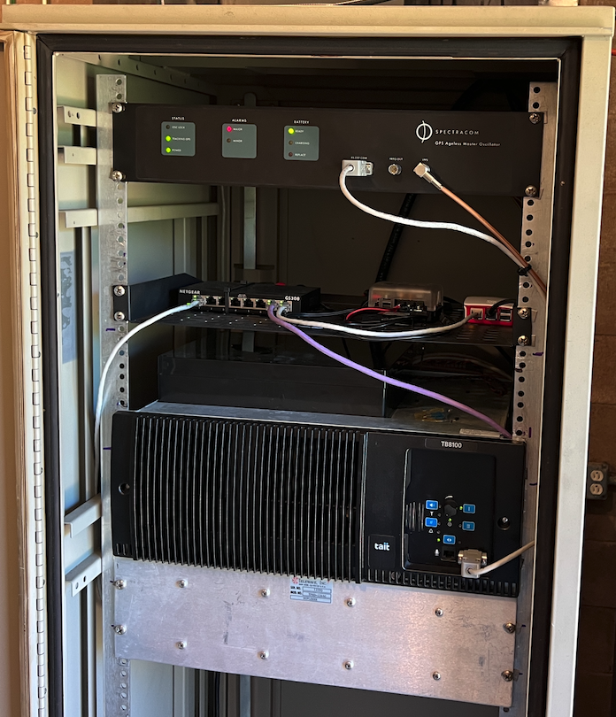
- Rpi running ASL3
- GPSDO Spectracom 8195
- Tait TB8100 VHF repeater
- SV-180 Simulcast Controller
- Ubiquiti Networks USG (site router not pictured)
- Telewave duplexer and antenna system.
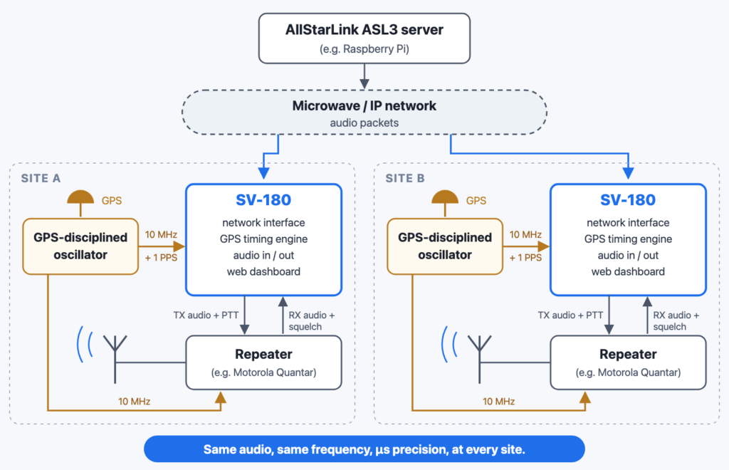
Putting several transmitters on one frequency on purpose means managing interference instead of avoiding it. This post touches on the theory behind simulcast, and how coverage and timing are tuned in a real system.
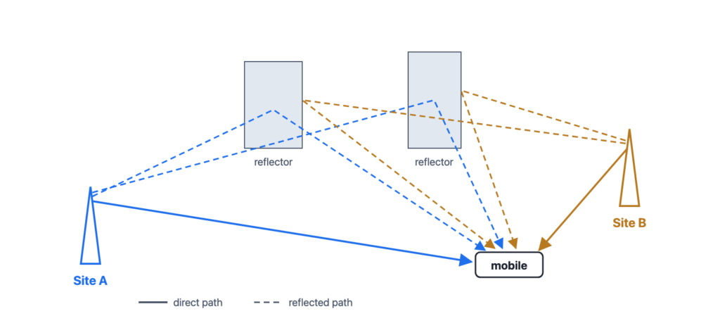
Every mobile radio already deals with interference from its own signal. At a single site, the signal reaches the radio by a direct path and also by reflections off buildings and terrain. The reflected copies arrive a little later and at a different strength. This is ordinary multipath, and receivers handle it every day.
Simulcast adds more of the same. A second site on the same frequency is, from the radio’s point of view, one more source of “reflections”: its direct path and its own reflections all land on top of the first site’s. This is co-channel multipath interference. The job of simulcast design is to keep that interference under control, so that where two sites overlap the radio still recovers clean audio or data.
A receiver amplifies what arrives at its antenna, mixes it down to an intermediate frequency, and demodulates it. When two or more signals are on, or very nearly on, the same frequency, they go through the mixer together and come out combined. Distortion is added along the way. What the radio finally produces depends on how its demodulator handles that combined signal. Everything else in simulcast design exists to make sure that combination still demodulates cleanly.
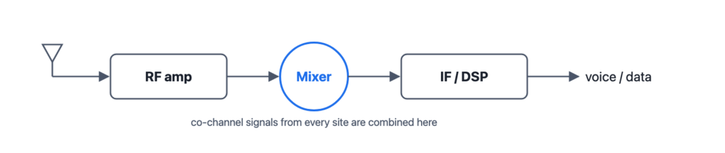
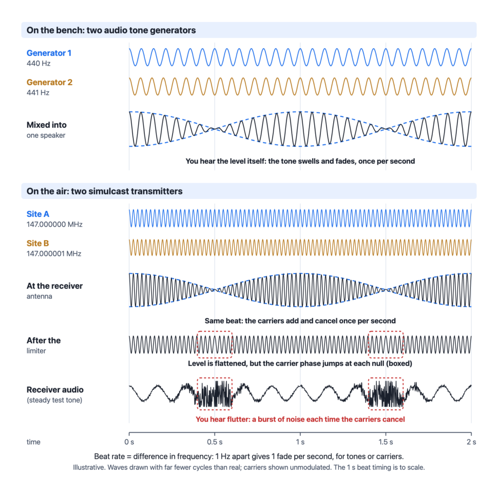
A mixer produces the sum and the difference of the signals fed into it. Put two transmitters at 147.000000 MHz and 147.000001 MHz, only 1 Hz apart, and the receiver sees a 1 Hz difference product. That is heard as a rolling fade, sometimes called “mobile flutter”.
Being frequency-locked is not the same as being phase-locked. To a receiver, a small change in phase looks just like a change in frequency, so a slow phase drift between sites also shows up as a rolling fade, and there is little that can be done about it at the receiver.
You can reproduce the effect on a bench with two audio signal generators. Set one to 440 Hz and the other to 441 Hz at the same level, and mix them into a single speaker. The combined tone swells and fades once per second, because the two waves drift in and out of step, adding together and then cancelling. The beat rate is simply the difference between the two frequencies. Two carriers at 147.000000 and 147.000001 MHz beat at the same 1 Hz as the two tones.
This analogy has a limit. In the radio the beat happens to the RF carrier, before the audio is recovered. An FM receiver ignores changes in signal level, so the listener doesn’t hear a smooth swell. They hear the audio flutter and break into noise each time the two carriers cancel. Try turning one generator down: the fade becomes shallower. That is the capture effect at work, as described below. When one signal is much stronger than the other, the weaker one can barely pull it down.
Note: the demo needs both tones summed into one speaker or one channel, not one tone in each ear.
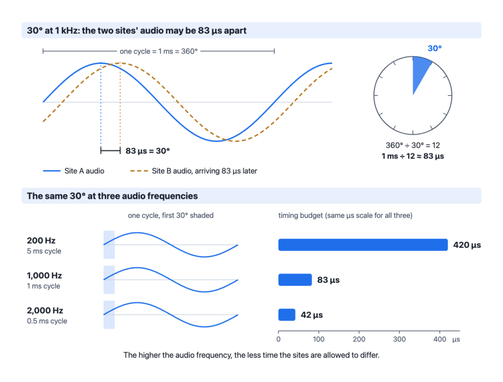
The decoded audio from each transmitter has to reach the radio within 30 degrees of phase of each other. Turning that into a time depends on the audio frequency. Using 1,000 Hz as the reference:
| Audio frequency | Period | 30° timing budget |
|---|---|---|
| 200 Hz | 5 ms | 420 µs |
| 1,000 Hz | 1 ms | 83 µs |
| 2,000 Hz | 0.5 ms | 42 µs |
The higher the audio frequency, the tighter the budget.
The same effect applies to data. For digital modulations, the limit is expressed as delay spread, and refers to the bit-error-rate versus delay-spread curves in TIA TSB-88. These show the error rate climbing as the delay spread between sites increases, with some modulations tolerating much more spread than others.
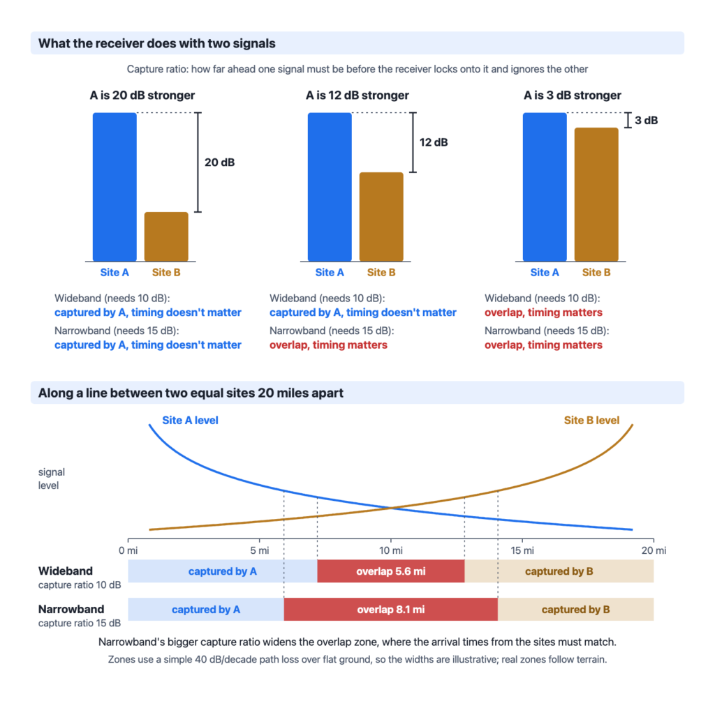
An FM detector will capture the stronger of two signals when their levels are different enough. It locks onto the stronger one and largely ignores the weaker. The narrower the deviation, the less capture effect there is.
This defines where timing matters. An overlap area is a place where no single transmitter is strong enough to capture the receiver. Only there does the delay between sites need to be managed. The thing that matters is the delay difference inside the overlap areas, not the distance between the transmitters.
Radio travels at about 5.4 µs per mile. That sounds quick, but the miles add up: 10 miles is 54 µs and 20 miles is 108 µs. Compare that with the 83 µs budget at 1 kHz. A path-length difference of 20 miles is already too much if the receiver is in an overlap area.
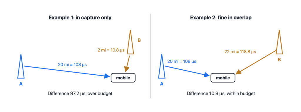
| Example | Path lengths | Arrival difference | Result |
|---|---|---|---|
| Two sites, mobile close to one | 20 mi / 2 mi | 97.2 µs | OK only if the near site captures the receiver |
| Two sites, mobile roughly equidistant | 20 mi / 22 mi | 10.8 µs | OK both in capture and in overlap |
| Three sites (C, A, B) | 40 / 10 / 5 mi | 189 µs (C–A), 27 µs (A–B) | A radio might be in overlap with all three. Avoid this by controlling coverage. |
The three-site case is closer to the real world. A pair of nearby sites can be well matched while a distant site’s signal arrives far too late. The is answer is to control where each site’s coverage goes, so a radio isn’t left in overlap with a far-off site.
SVRG’s analysis. This section works out the effect out from basic two-signal FM theory, and the second figure comes from a simple computer simulation, not a field recording.
Drive through an overlap area where both sites are strong and the audio can take on a rapid, rhythmic flutter: a fast chop or warble, not hiss. It speeds up as you speed up and goes away when you stop. With our two test sites setup you can clearly hear this effect driving north, toward one site and straight away from another site to the south, along the hwy 101 corridor in Morgan Hill.
This is the “mobile flutter” from the carrier section, but here the motion makes it, not the transmitters. Even with both carriers locked to exactly the same frequency, a moving radio hears each one shifted slightly by the Doppler effect. Driving toward Site N, its signal arrives a little high, by the car’s speed divided by the wavelength. Driving away from Site S, its signal arrives low by the same amount. At 30 mph on 147 MHz each shift is 6.6 Hz, so the receiver sees two carriers 13.2 Hz apart. That is no different from two transmitters 13 Hz off frequency: the combined signal fades in and out 13 times a second.
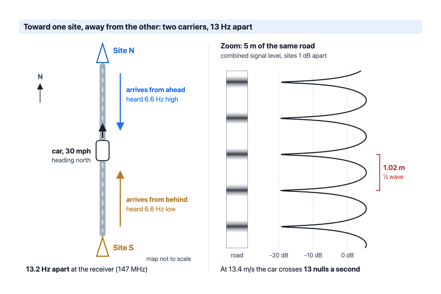
There is a second way to see the same thing. Where two signals cross, they add in some places and cancel in others, and that pattern stands still on the ground. When the two signals come from opposite directions, the cancellations (nulls) are half a wavelength apart: 1.02 m at 147 MHz, 0.34 m at 445 MHz. The car simply drives through them. At 30 mph, 13.4 m/s ÷ 1.02 m gives the same 13 nulls a second.
| Band | Null spacing | 5 mph | 30 mph | 60 mph |
|---|---|---|---|---|
| 147 MHz | 1.02 m | 2 Hz | 13 Hz | 26 Hz |
| 445 MHz | 0.34 m | 7 Hz | 40 Hz | 80 Hz |
The table is the fastest case, with one site straight ahead and the other straight behind. If the sites are not on opposite sides of you, the nulls are farther apart and the flutter is slower. Drive across the line between two sites instead of along it, and both signals arrive from the side: neither is Doppler-shifted much, and the flutter should all but stop. The same standing pattern is why a handheld user in an overlap can sometimes clear up the audio by moving a foot or two.
Why it is a flutter, not hiss. An FM receiver’s limiter strips off changes in amplitude, so the dips themselves aren’t heard as long as the signal at the bottom of each dip stays well above the noise. With both sites strong, it does. Two signals 1 dB apart dip about 19 dB, and two signals 0.3 dB apart about 29 dB; a strong signal 20 or 30 dB down is still a usable signal. What the limiter can’t remove is the phase of the combined signal, which swings quickly each time the two carriers pass through opposition, and that swing is what reaches the audio. When the two signals also fade on their own and trade places as the stronger one, the combined phase can slip a full turn, which is heard as a sharper pop.
Audio timing decides how bad it sounds. If both sites’ audio arrives at exactly the same moment, both carriers carry identical modulation and the phase swing at each dip is brief and small. In the simulation below, with the levels 1 dB apart, the receiver’s tone comes through clean, dips and all. If the two sites’ audio arrives a time τ apart, the modulation itself rocks the carriers’ relative phase back and forth, by about 360° × peak deviation × τ. At 2.5 kHz deviation and 80 µs, the narrowband delay limit in the design criteria above, that is ±72°. Whenever the slow 13 Hz rotation brings the two carriers within 72° of opposition, the audio pushes them through cancellation again and again, and the waveform is torn up. That covers 144° of every 360°, about 40% of each flutter cycle. The simulation agrees: measured in 1 ms slices, 43% of the audio falls below 20 dB SINAD, in a burst around every dip.
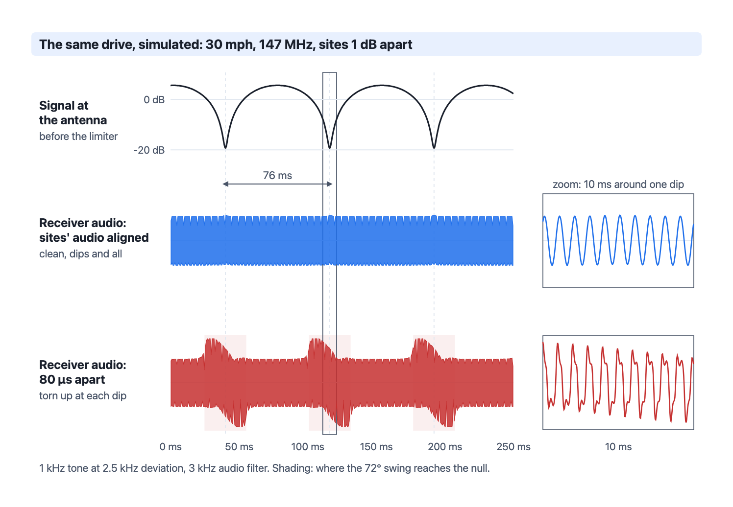
So the motion sets the rhythm, and the alignment sets the damage. A difference in deviation between the sites rocks the phase the same way, most at low audio frequencies: a 10% mismatch on a 300 Hz tone at full deviation is about ±48°. The case simulated here is the worst corner of an overlap area, with the delay right at the design limit and the two signals within about a dB. It shows why delay and deviation are worth matching as closely as the equipment allows, and why it pays to know where the overlap areas fall.
A coverage-prediction program for simulcast has to calculate time-delay interference as well as signal level. Design criteria:
| Modulation | Capture ratio | Maximum delay |
|---|---|---|
| Wideband analog FM | 10 dB | 80 µs |
| Narrowband analog FM | 15 dB | 80 µs |
| P25 C4FM (DAQ 3.4) | 15 dB | 30 µs |
| P25 LSM (DAQ 3.4) | 15 dB | 70 µs |
With those two numbers, a prediction can mark each place as either captured by one site (more than 15 dB stronger than the others, so delay doesn’t matter) or in overlap (where the arrival-time difference has to be within the delay limit). Because narrower deviation gives less capture, deviation is one of the inputs that moves the overlap areas.
Tilting a site’s antenna down clearly raises signal levels close to the site. It reduces the areas of overlap interference, but at a cost. High sites lose some of their wide-area coverage, so talk-out is reduced in some places. Simulcast from high sites is often difficult, and much of the reason for choosing a high site goes away once its coverage has to be pulled in.
You can’t tune a simulcast system by driving around. You need to model it in software.
Salinas Valley Repeater Group uses its own in house modeling software to calculate and map the delay spread for our simulcast system. A delay spread map lets us visualize the differential delay or ‘delay spread’ within the designed coverage area of our system.
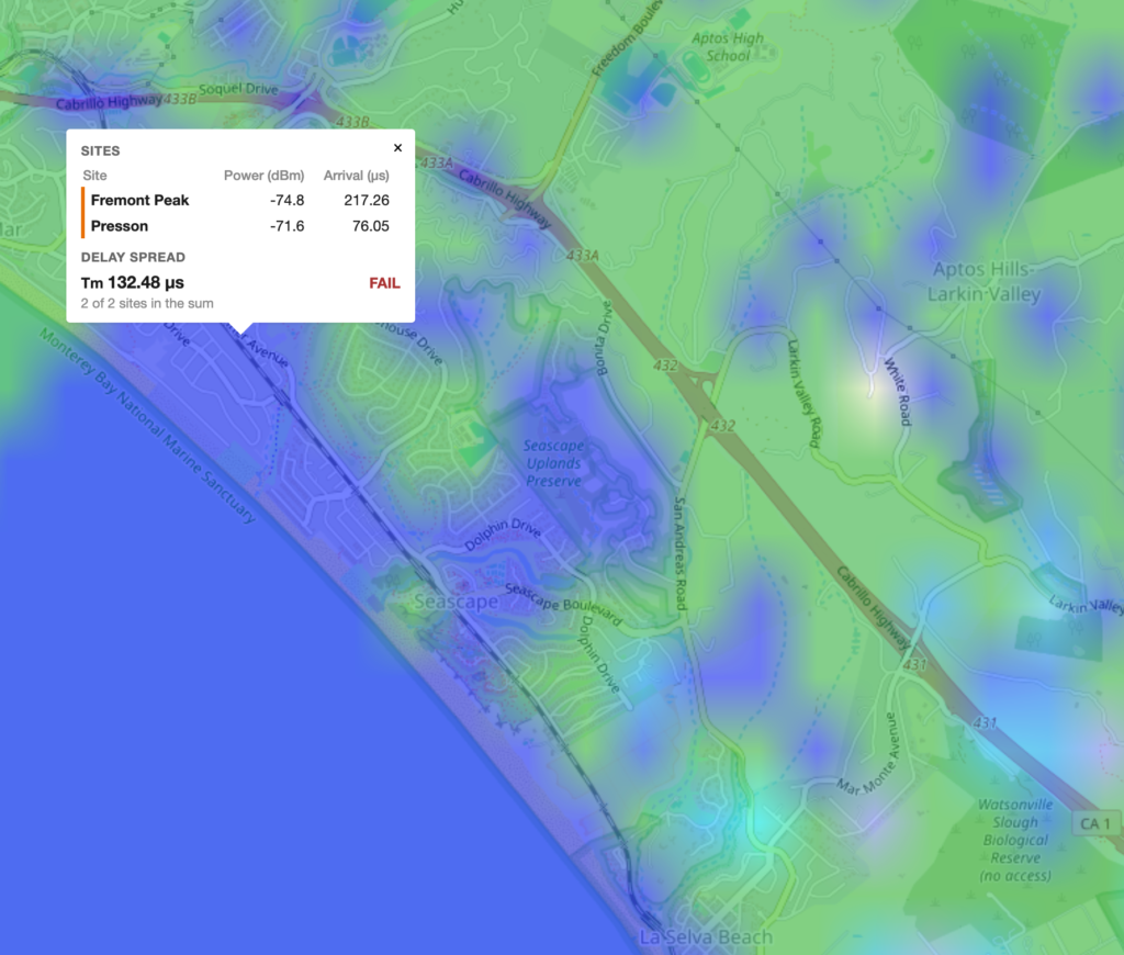
The map pictured shows an area in Santa Cruz County that will be out of our phase budget so the resulting signal in this area will have distortion artifacts.
This week was historic for the Salinas Valley Repeater Group, on Thursday 9/24/2026 we put our first simulcast system on the air!
Over the last 7 years, I’ve been wanting to convert SVRG’s linked system to simulcast. But why simulcast you ask? These systems are hard to build, maintain, and are complex to design. Well let me list out some of the advantages and disadvantages of a simulcast system and you’ll see why I’ve wanted to bring an open VHF simulcast system to the amateur radio community.
All that said, the goal was set. Simulcast was the path forward for SVRG, but how would it be built? Our first experiments were with the Motorola DSM-II T1 based simulcast system developed in the 90’s. After building a test system of 3 sites and mulling over the installation requirements, rackspace constraints, T1 circuit emulation TDMoP, 48v DC power systems. It became quickly apparent that a DSM-II based simulcast system would not be feasible for the system we wanted to build.
DSM-II is off the table, so I started to look into the Motorola MLC-8000 and Micro-Node RTCM. The MLC-8000 requires a 5Mhz 1PPS composite signal that the TRAK-9100 produces (very costly) and the Micro-Node RTCM requires hardware modification to use for simulcast as it requires a 9.6MHz non standard clock, so that’s out too.
Our solution was to design our own simulcast hardware! Dub’d the SV-180, our simulcast board connects to ASL3’s linking and voting platform like the RTCM. More to come on that in another post.
As of right now our plan is to convert all VHF systems to simulcast on 1 frequency pair (excluding Meadow lakes VHF).
This in and of itself is going to be a bigger challenge to work out than the engineering required to design our own simulcast controller and build out a system over multiple counties.
Due to the frequency congestion on the VHF band in our area and with our plan being very aggressive, coupled with the fact that there is no perfect frequency pair for us to land on.
We ask for understanding that while we continue to test and develop this repeater system.